
Disclaimer:
This workguide has been prepared in good faith. This is a technique that the author has used to work on this part of the vehicle. This may or may not work for you. fxfjholden.com and the author of this publication will not be held liable for any personal injury, damage to property or vehicle if this guide is used. This guide is to be used at your own risk.
This is a work guide on refurbishing a king pin. Although it is a king pin of 1938 Buick, it is very similar and still the same process as an FX or FJ one. Many thanks to Paul Calder for creating this guide.
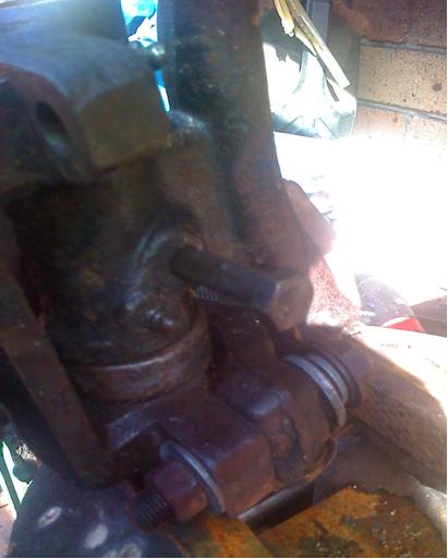
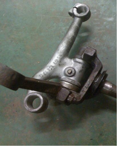
The steering knuckle and hub assembly, still complete. Threaded cotter pin being removed to allow king pin to be removed.
The steering knuckle and hub assembly, still complete. Threaded cotter pin being removed to allow king pin to be removed.

Secure the assembly in a vice. Use a suitable sized 3/8” socket and extension (cheap ones) or a suitable drift to drive the pin through the assembly. Most vehicles have a bearing and shim above the lower pivot. Once the pin is removed the assembly will fall apart.
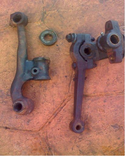 The steering knuckle and axle hub separated by removal of the king pin. The cotter pin and shim are not shown.

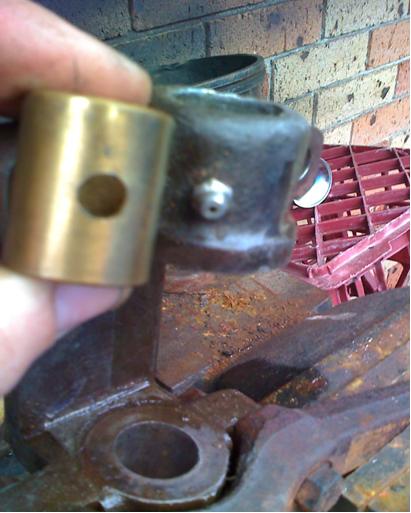
The worn, upper, bronze bush. These are a sacrificial part and wear is expected. The bushes are made of a softer material so the steering components and housings do not wear, that is the idea any way. After seventy years the steering knuckles on this Buick are a little worn, causing movement in the knuckle, which combined with the worn King Pin’s was causing a dramatic amount of movement.
The passenger side usually wears first due to hitting pot holed road edges.
A suitable sized socket being used to drift the old bush, they should come out with light blows of the hammer.
Socket being used with extension to facilitate removal of lower bush.
The hub has been cleaned up and the new bush is ready to fit. Pay attention to the location of grease holes. This one is to be lined up inside the bore of the hub with the grease nipple in the foreground.
Tap lightly with a nylon or wooden mallet to align the bush into its new home. If you’re keen you can machine a tool to sit nicely in the top of the bush and use a hammer to drive the bush home. Otherwise, a nylon or wooden mallet or piece of timber will suffice to get the bush in. Once level the socket can be used to drive the bush slightly further. Aim to have the bush flush with the inner surfaces of the hub. Some King Pin kits come with caps to seal the top, if the bush is left too high these will not fit, resulting in grease leaking out.
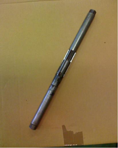
This is a reamer. These can now be bought quite cheaply (around $50) and will last forever if looked after. A complete kit can be had for around $250 dollars. They are adjustable by loosening or tightening the lock nuts visible at the bottom of the blades.

This is a guide. It slips over the shaft of the reamer and keeps the reamer straight by slipping into the opposing bush of which you are working on.

The guide in position on the reamer.
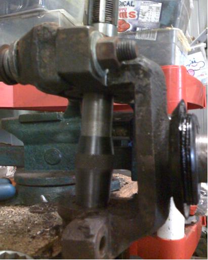
The lower bush is being reamed. The guide can be seen resting in the opposing bush. The blades at the top have not yet made contact with the bush. WD40 is a good lubricant to use whilst doing this work.

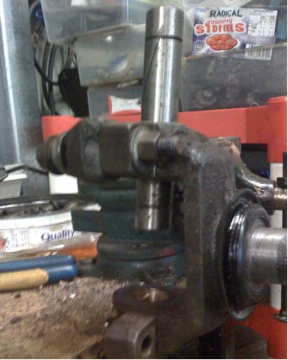
The top bush is now being reamed using the bottom bush as the guide. Make small adjustments with the reamer, if you go too far you can’t put material back. The KP should be a snug fit and push through the bushes with a small amount of resistance. If you leave them too tight your steering will be heavy and will not self correct, it will tend to grab into whatever position you are holding the wheel. If you are using KP’s with power steering they can be left marginally tighter.
The KP is now a snug fit requiring a small amount of force to push it through. There is no lateral movement at all.

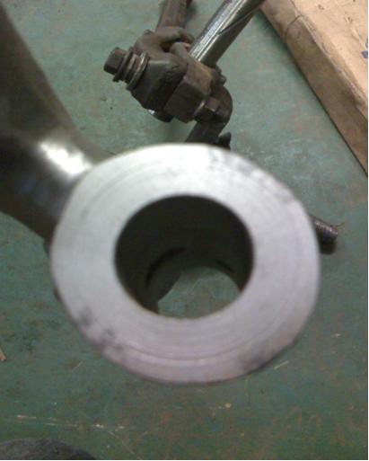
I was lucky to find some NOS steering knuckles for the Buick. Seventy years and a poor fitting cotter bolt had taken its toll on the old ones. There was noticeable movement between the bore and kingpin on the knuckle. There is no bush in this section as the cotter pin is supposed to lock the shaft tight in this section with the hub pivoting on either end. The shaft should not move at all. ANY movement in this section will cause problems in years to come.
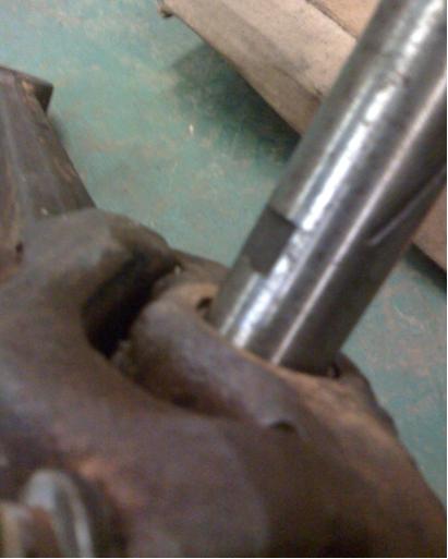
When being assembled pay attention to the machined groove on the pin. The pin will be tight once driven through the entire assembly. This groove must line up with the hole in the steering knuckle pictured next.
Internal view of cotter pin hole in the steering knuckle. The King Pin groove must line up with this hole.

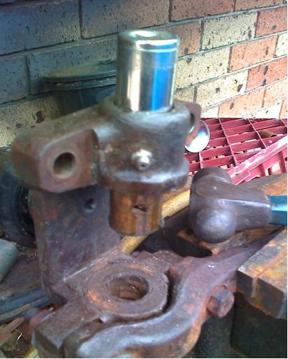
The king pin has been driven through the assembly and the cotter pin is being inserted to locate the pin. Note the bearing below the cotter pin. A shim is located under the bearing to remove any up and down movement. Shims are usually supplied with king pin kits.
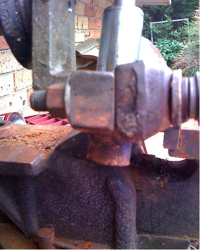
The completed assembly, ready for greasing.
There is zero detectable movement in this assembly. Try and be as accurate as possible and aim for zero movement. ANY movement in the king pin assembly will cause accelerated wear as that point as it will continually be hammered by suspension movement.
I also recommend replacing the grease nipples when this work is carried out.
This procedure, not including the removal from the car, took around 45 minutes.
Courtesy of Paul Calder